M. JAHIN
Blue Sky Mining Corporation (Remote Site Coalmine Network Architecture)
Blue Sky Mining Corporation: Remote Site Coalmine Network Architecture

Project Location: Wolverine Creek, Yukon, Canada
Project No. BSMC 2024.04/05-0200
Created By-
Md Muhtashim Jahin (Network Engineer)
Krish Lakhan (ICS Specialist)
Sina Faraj Poor (GRC Analyst)
Puvit Srithep (Project Manager)
Introduction
In an elastic cyber-construct that happens 10 years from now; you are part of an engineering design team for a green field copper, zinc and lead mine. Your Client, The Blue-Sky Mining Company (BMSC) world headquarters are located in Vancouver, Canada. BSMC has four active mining sites they are in Silobela, Zimbabwe; To Anua, New Zealand; Katherine, Australia and Igarka, Russia, and two virtual mining sites that reside in Azure servers located in Redmond, Washington.
Scope of Work
My design team is responsible for the network design and architecture for both the OT and IT networks for the entire Wolverine Site. Each team will need to provide the following:
- Engineer a converged IT & OT Coalmine Network Architecture drawing,
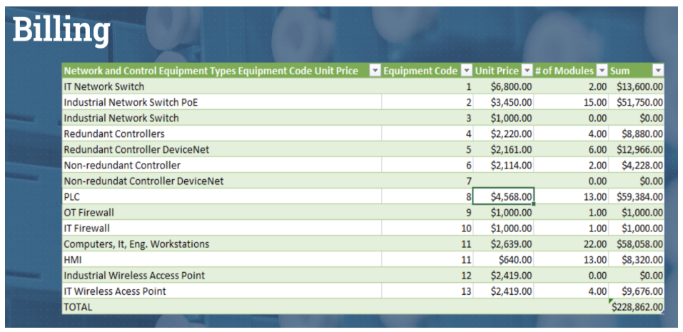
- Develop an itemized bill of materials, including the cost of all equipment,
- Author & compile all specification sheets for the network equipment, enclosures, and cables that will be required to construct the site network.
Equipment Count
Here’s a complete count of all the devices and systems identified across the different operational zones:
- VoIP Telephones: 22
- CCTV Cameras: 16 (includes network connections for outdoor PoE cameras and video cameras)
- IT Computers: 18
- Engineering Workstations: 4
- Human-Machine Interfaces (HMIs): 11 (includes redundant pairs and standalone units)
- Programmable Logic Controllers (PLCs): 23 (covers various control applications from pumps to generators, including redundant pairs)
- Underground Communication System (Fiber Optic Ethernet Interface): 1
- On-line X-ray Fluorescent Analyzers: 3
- Environmental Monitoring Analyzer: 1
- IT Wireless Access Points: 3
- Data Historian Servers (Redundant): 2
- Control System Database Servers (Redundant): 2
- IoT Coffee Machine (Wireless Enabled): 1
Equipment List
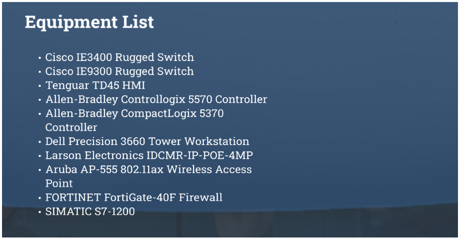
Project Background
Project Description
The project is greenfield, and is located at Wolverine Creek, Yukon, Canada. The site is remote, and will use 5 – 20 MW diesel generators for site power; there are no land lines (power or communications) that connect the site to the outside world. A 55 km haulage road is under construction; it will connect to Hwy, 66 at km 55, and provide access to Kitimat, BC for overseas shipment of the ore concentrates. The site layout drawings are as follows.
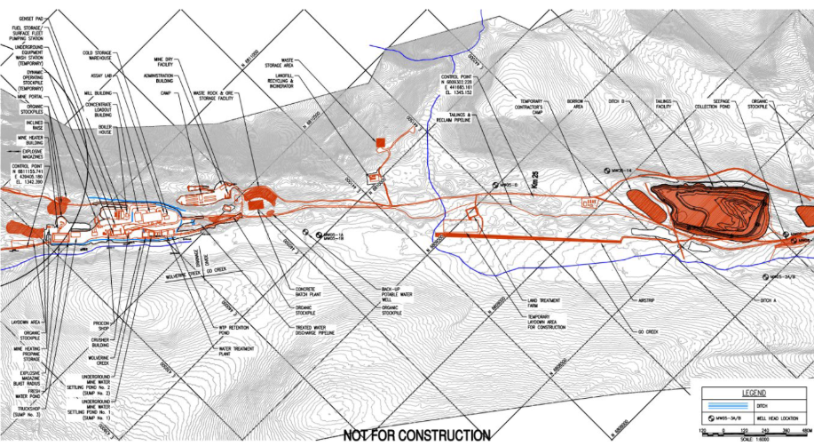
General Site Layout Plan
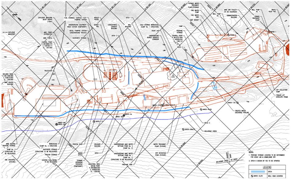
Industrial Complex General Arrangement Plan
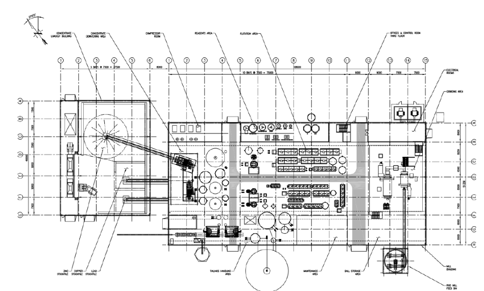
Milling Building and Concentration Loadout Building Layout Plan
Site Environmental Data
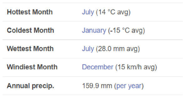
The lowest recorded winter temperature at the site is -60 °C, and the highest on record summer temperature is 35 °C.
Deliverables and Design Criteria
Network architecture drawing design criteria.
- The drawing will be divided into zones, each zone will show the relative location
of the equipment, enclosures and patch panels.
- Using the Client’s wire colour code, the connections between all equipment and
network switches located in the zones will be shown on the drawing. Your
design should include a 15% contingency for future expansion.
- You will need to specify the number of fibers that will be use in the main trunklines,
the type of cable used and which fibers are used to service each of the
zones.
- The specification sheets for all network switch equipment, communication
cables and fiber optics, used throughout the network needs to be included with
your submission. The cable specifications will need to be cross-referenced to
locations where the cables are used in your Network architecture drawing.
Bill of Material design criteria.
- All equipment used in the design will need to be included in the BoM.
- The BoM will be divided into zones.
- Each line item in the BoM will contain the following information.
- The equipment ID code, as per the Client’s Equipment ID
requirements.
- A general description of the equipment.
- And equipment prices as per the Client’s price list.
- Summarize the total project cost based on the equipment cost for each zone.
Client’s Project Standards
To maintain consistency across all their sites, the Client has chosen to apply their corporate engineering standards to this project. Proposal submissions must use the following Client standards.
Equipment IDs
For asset tracking, the Client uses a cloud-based SAP system, the system which allows BSMC to assign a unique ID number to all their assets.
The following table shows the asset tracking number schema for this project:
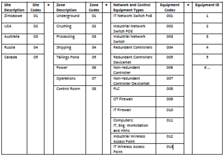
For example, Asset 05.05.006.1 is located at the Tailings Pond on the Wolverine Site and is a Single (Non-Redundant) Controller that is labelled as asset item number one.
All the project equipment will need to be identified by its asset number in the architectural drawing and the bill of materials that are part of the deliverables.
Network Architecture
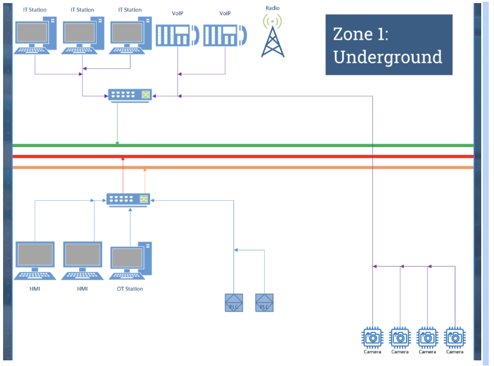
Zone 01 – Underground
- The Top-side Mining Office is located about 50 m South of the Mine Portal. The office is
used for Safety, Control and Administration purposes. The office will contain the
following equipment,
- 2 VoIP telephones,
- Network connections for 4 outdoor PoE CCTV Cameras,
- 3 IT computer,
- 1 Engineering Workstation,
- 1 pair of redundant HMIs for the Top-side operator,
- 1 pair of redundant controllers for the mine sump pumps, mine lift and mine
ventilation systems. Note, all control equipment will be located top side as the
humidity underground will be too high.
- The underground communication system is located underground, the radio
system will have a fiber optic Ethernet interface. The radio emergency channel
will need to be monitored in the Top side office and from both the Site Safety
Office and the Control Room.
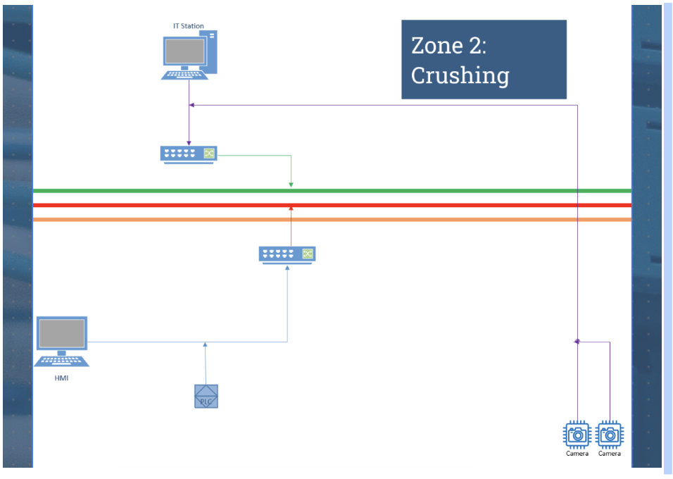
Zone 02 – Crushing
- The Crusher Building is located about 50 m South-East of the Mining Office.
- A 250 m conveyor with 2 x 125 m sections will be used to transport the ore from the Crusher Building to the grinding section of the Milling Building, the conveyor will be controlled by a PLC. There are 2 video cameras located at the transfer point between the two conveyors and at the discharge to Rod Mill Feed Bin.
- A small Operator cab will be located over top of crusher infeed. A Robotic arm jack-hammer, includes a vendor supplied PLC and HMI. The PLC will supply preventative maintenance data from the robot to the predictive maintenance system. The operators cab will contain 1 IT computer (email, etc.), and 1 HMI computer.
- Crushing will only be operated during the day shift. There are no requirements for redundancy, but the controller will need to be connected to the main control network for interlocks and up-loading of the crusher’s production data to the Process Data Historian.
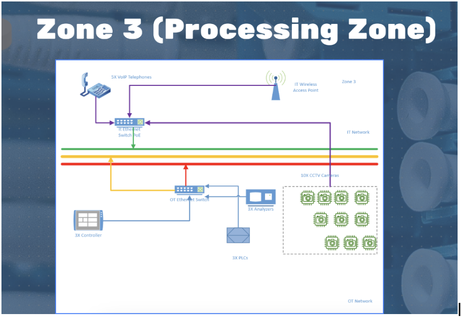
Zone 03 – Processing
The Mill Building is located 50 m North-East of the Crusher Building. The processing operations will be required to run 24/7/365, for the first year of operations. A cloud based predictive maintenance system will be used to schedule the equipment maintenance.
This area contains the following equipment,
- 3 pairs of redundant controllers that support DeviceNet will be used to control each of the following areas, o Grinding, o Flotation, o and Concentrate Thickening.
- 2 PLCs will be used on the vendor skids for the following equipment, o Rotary Drum Vacuum Filter, o Paste Backfill Plant.
- 3 on-line x-ray florescent analyzers with Ethernet NICs, one per flotation line. (copper. lead and zinc).
- 5 VoIP telephones located at unspecified locations on the plant floor
- 1 PLC for HVAC
- 10 CCTV cameras
- IT Wireless access point
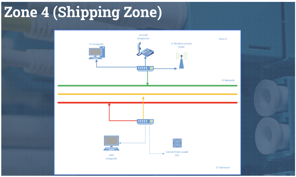
Zone 04 – Shipping
Operated only during day shift.
This area contains the following equipment
- 1 PLC that operates the concentrate loader
- 1 HMI computer
- 1 IT computer
- 2 VoIP telephones
- A wireless access point is required, as the Drivers will need to access their email.
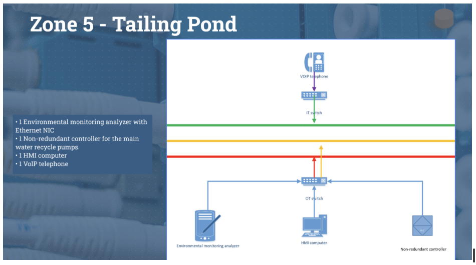
Zone 05 – Tailing Pond
This area contains the following equipment,
- 1 Environmental monitoring analyzer with Ethernet NIC
- 1 non-redundant controller for the main water recycle pumps.
- 1 HMI computer
- 1 VoIP telephone
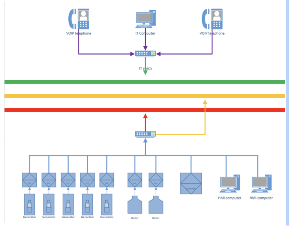
Zone 06 – Power
This area contains the following equipment,
- 5 – Cummings 20 MW diesel generator, switch gear. etc., systems are stand-alone and will run 24/7/365. Controlled by 5 separate vendor-supplied PLCs tied to vendor vendor-supplied control LAN. Alarms, trips, operational data. etc., from the power system will need to be tied into the plant control system.
- 2 packaged vendor-supplied boilers, 24/7/365 operations, 2 PLCs, supervisor data and alarms needed by the operators in the control room.
- 1 non-redundant controller
- HMI computers
- 2 VoIP telephones
- 1 IT computer
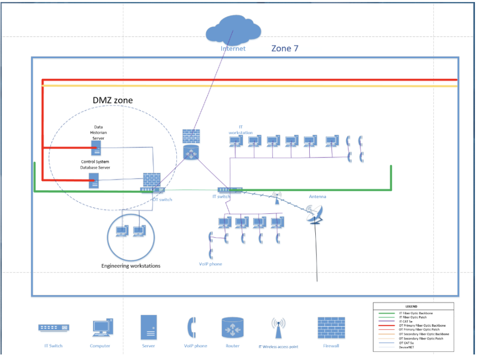
Zone 07 – Offices
This area contains the following equipment
- 1 Data Historian Server – redundant
- 1 Control System Database Server – redundancy
- 10 IT computers, site video feeds, SAP, ERP, video communication with headquarters, and the Safety Department will need to monitor the underground radio emergency channel
- 2 Engineering workstations
- 10 VoIP telephones
- The Client will tender the bid package for the satellite communication system under a separate PO than the one being issued for the OT and IT network of this project.
- IT Wireless access point
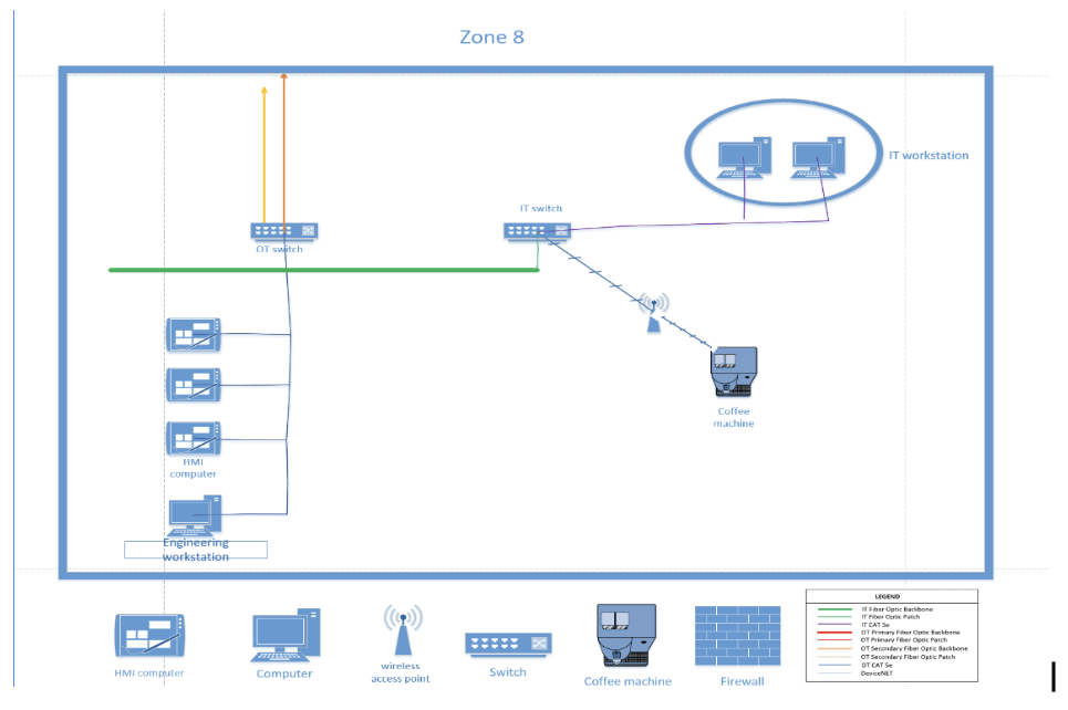
Zone 08 – Control Room
This area contains the following equipment,
- 3 Redundant operator HMI computers
- 2 IT computers for site video feeds, email, etc.
- 1 Engineering workstation
- 1 IoT coffee machine (wireless enabled)
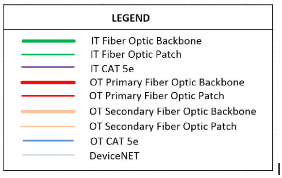
Wire Colour Coding
The Client also uses the following colour code schema to identify their network cables:
Bill of Material design criteria.